
Shaft Alignment in Ship Engines: keys to optimum performance and efficiency in seagoing navigation
Proper operation of the ship's engine is vital to ensure efficient and safe performance in marine navigation. Among the fundamental aspects to achieve this is the proper alignment of the propeller line shaft.
Discover in this article the importance of shaft alignment in all its aspects and how it influences the overall performance of the vessel.


What is marine shaft alignment
Shaft alignment is a mechanical procedure by which a specific positioning of the shaft and the other components of the propulsion line, such as the gearbox or the marine propeller, is carried out in order to verify that the shaft is perfectly aligned and in the correct position.
Shaft alignment is an essential aspect to take into account as it allows for greater efficiency and longer engine life and avoids problems related to coupling and bearing wear, vibrations and friction between elements, as explained below.
Importance of prop shaft alignment:
- Efficiency and performance: Precise alignment of the engine shaft ensures optimum transfer of energy and power from the engine to the propulsion system. This allows the ship to operate efficiently and achieve optimum performance in speed, maneuverability, and responsiveness.
- Vibration and noise reduction: Incorrect shaft alignment can cause unwanted vibration and noise during engine operation. These vibrations affect the comfort of crew and passengers and can cause premature wear on propulsion system components.
- Preventing damage to components: Improper shaft alignment can place additional forces and stresses on propulsion system components such as the shaft, bearings, transmissions, and propellers. Such friction can lead to premature damage, excessive wear, and equipment failure. Accurate alignment helps prevent these problems and prolongs component life.
- Energy and fuel savings: Correct alignment of the engine shaft reduces friction and drag, which results in lower fuel consumption. By minimizing energy loss due to poor alignment, efficiency is optimized and significant economic and environmental savings are achieved over time.
Shaft misalignment: a common problem that is easy to spot
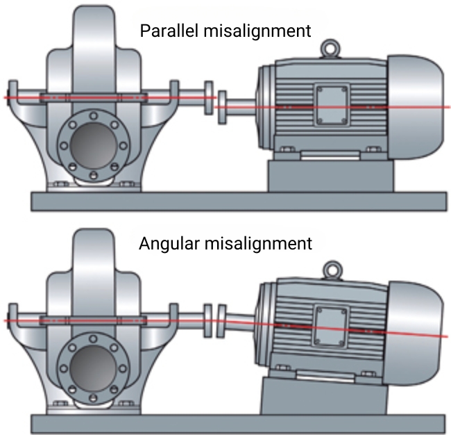
As we know, shaft misalignment can lead to problems in the machinery and consequently in the sailing performance. To detect it, two types of shaft misalignment can be identified: parallel misalignment and angular misalignment.
- Parallel misalignment of the marine shaft: the center lines of the inverter output shaft and the shaft are parallel, but are vertically separated by some distance.
- Angular misalignment of the shaft: the center lines of the inverter output shaft and the shaft form an angle.
- It is also possible to have a combination of both.
What can we do to avoid this misalignment?
Once the engine is installed on the bedplate, it should be positioned so that it is as aligned as possible. To this end, we recommend:
- Use a bushing of the same diameter as the shaft in order to align the shaft with the horn and finally move the motor to the most aligned position possible.
- Raise or lower the jockstrap nuts. In this way, the height of the motor can be adjusted so that the output shaft of the inverter is at the same level as the shaft and can be correctly coupled.
Once the engine has been positioned, the alignment must be finalized more precisely using one of the most common methods explained below.
Propeller shaft alignment methods
Alignment method using gauges
One of the traditional methods for shaft alignment is the use of gauges to measure the clearance between the output flange of the inverter or flexible coupling and the shaft flange.
The procedure to follow is to insert the gauges at various points between the inverter flange and the shaft flange and rotate the shaft until the gap between the two is equal at all points. In addition, the recommended limit should be respected, which is that the 0.10 gauge should not fit between the two flanges at any point.
In case the measurements are not within the acceptance range, appropriate adjustments are made to the motor or shaft position.
The advantage of this type of alignment is that it is simple and quick, although it is the least accurate.
Alignment method using a dial gauge
This second method is not as popular as the previous one as the process is not as fast, but its advantage is that it offers greater accuracy.
The first thing to do is to place the instrument at a fixed point on the inverter flange and its contact tip on the shaft flange. Before the shaft is rotated, the zero position shall be marked on the dial gauge. In this way, when the shaft is rotated one full turn, the clock will show the total deviation between the two.
The existing deviation shall be corrected and the position of the motor and shaft adjusted until the indicator shows a deviation of zero millimetres. In this way, precise shaft alignment is achieved.
Laser alignment method
This is one of the most modern methods of shaft alignment. This method provides more precision and automation than traditional procedures. In order to carry out the alignment with this system, you must acquire a pack with the following devices and have the necessary training to know how they work:
- Two measuring units (laser beam emitter and detector).
- Display screen.
First, the beam emitter must be installed on the fixed axis and the prism that will detect the beams must be installed on the movable axis. These devices shall be connected to the digital display, on which the measurements taken and misalignments at the measurement points can be displayed. In addition, they also indicate the corrections to be made. In this way, the positions of the shafts can be rectified and the necessary measurements can be taken again until the display shows the correct alignment.
And finally, let's look at the process of aligning the shaft
Now that we know the importance of shaft alignment and we have seen the different measurement techniques, let's look at the general steps to carry out the alignment:
- Initial inspection: Prior to alignment, the condition of the propulsion system components, including the shaft, bearings, transmissions and propellers, should be inspected and assessed. It is important to ensure that there is no significant damage or wear that could affect the alignment.
- Measurement and adjustment: Measuring tools (seen in the previous section) are used to assess the position and alignment of the shaft in relation to other components. These measurements help to identify any misalignment and determine the necessary adjustments.
- Adjustment of brackets and bearings: If misalignment is detected, the shaft supports and bearings are adjusted. This may involve loosening or tightening the fixing bolts and making changes to the position of the brackets until the correct alignment is achieved.
- Final verification: Once the adjustments have been made, a thorough check is carried out to ensure that the shaft alignment is accurate. This involves re-measuring and checking the position of the shaft in relation to the other components.
Ultimately, proper shaft alignment in ship engines is essential to ensure optimum performance, reduce vibration and component damage, and achieve energy and fuel savings.
We recommend that you have your marine engine serviced regularly and carefully and that you entrust the maintenance of your marine engine to qualified personnel who are part of the Solé network of official workshops and services around the world.

